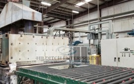

Make: Glasstech
Type: 84” Wide Tempering Furnace
Power: 460 Volts 3 phase AC Motor
Year: 2009
Location: Mid West USA
Condition: This furnace would be perfect for someone tempering clear or heavy glass- it’s got a fast cycle time. Furnace is in good working condition but it doesn’t work well with some triple silver low-E’s so the current owner can’t use it on some of their projects. Current owner has spent close to $200,000 in rebuilding and upgrading various parts of the machine.
Notes:
- Load Station
- Drive System
- Independently driven, single-ended 460 volt 3-phase AC motor.
- Belt drive system with a line shaft spanning the length of the conveyor, with pulleys and optical proximity sensor.
- Load table and main conveyor drive electronics are pre-wired and positioned under the load table
- Pop-up casters will be provided to aid in the loading of large glass sheets.
- Load Table Configuration
- Load Conveyor Length 4.27m (14ft.)
- Active Conveyor Width 2140mm (84in.)
- Roll spacing 152mm (6in.)
- Drive System
- Heater
- Forced Convection Heater
- 1.83m (6.0ft.) long forced convection heater sections. Furnace frames are of a rectangular form with stainless steel liners.
- Cast end walls including an insulating barrier at the conveyor interface with a door mechanism located at both the charge and the discharge end
- Leveling pads are integrated into the framework with a bolt adjustment that will set the heater’s elevation.
- Each upper hot fan is driven by a 15kW (20hp) 460 volt 3-phase 60Hz motor with inverter duty wiring and water cooled.
- Each lower hot fan is driven by a 12kW (15hp) 460 volt 3-phase 60Hz motor with inverter duty wiring and water cooled.
- Forced Convection Heater
- Heater configuration
- Heater Zones Qty. 3
- End door Assemblies Qty. 2
- Upper Hot Fans Qty. 3
- Lower Hot Fans Qty. 3
- Drive System
- Independently driven by a single-ended AC motor.
- Belt drive system with a line shaft spanning the length of the conveyor, with pulleys.
- Furnace rolls are equipped with pin style roll support and bearings on the end caps. Roll Spacing = 114mm (4.5in.)
- Roof Lift
- The lifting jacks will be mounted on the upper heater section and push down on the lower section to raise the roof
- Lifting points have coupling that can be separated to adjust the height independently of the four points
- The upper furnace can be raised approximately 355mm (14in.) clear of the lower furnace
- Each set of four lifting jacks are coupled to an AC motor
- Quench
- Quench System
- The entire upper quench can be raised and lowered for nozzle to glass height adjustments by screw jacks powered by an AC motor complete with linear position transducer for computer control
- Manual screw height adjustment is provided for the lower quench
- Both upper and lower quenches are equipped with air cylinders to open the upper and lower quench modules for clearing broken glass
- A manually adjustable pyrometer below glass line
- Manometer – digital display provided at quench panel and also on main screen at operator console.
- Quench Configuration
- Quench Type Side feed
- Quench Length 4.27m (14ft.)
- Active Quench Bed Reduction Damper pairs 2 (with rotary actuators, uppers and lower coupled together)
- Drive System
- Independently driven by a single ended AC motor
- Belt drive system with a line shaft running down the length of the conveyor, with pulleys. Roll spacing = 102mm (4in.)
- Unload Station
- Quench System
-
- Drive System
- Independently driven, single-ended 460 volt 3-phase AC motor
- Belt drive system with a line shaft spanning the length of the conveyor, with pulleys
- Unload table and quench conveyor electronics are pre-wired and positioned under the unload table
- Pop-up casters provided to aid in the unloading of large glass sheets
- Unload Table Configuration
- Unload Conveyor Length 4.27m (14ft.)
- Active Conveyor Width 2140mm (84in.)
- Roll Spacing 152mm (6in.)
- Drive System
- Control System
- Feature Set
- The control system is an Allen Bradley Controllogix™ PLC with an INTEL class computer user interface
- Capabilities of the control system include:
- Touch screen operator interface
- Remote modem communication for software updates and troubleshooting
- Heat time driven motion control
- Variable load length capability
- Ability to change recipes while processing current recipe without missing unnecessary loads
- Ability to vary heater reversal points for optical improvements
- Ability to stop quench at the forward quench position
- Automatic quench gap control
- Air test function with process override
- Process error logging to screen and file
- Process Production parameter logging to screen and file
- Feature Set
- Utilities and Control (Precise amount determined at engineering meeting)
- Electrical: 380 to 600 volt three-phase, fifty (50) or sixty(60) hertz, four-wire electrical power:
- Quench fan power (3mm): 675kW (900hp)
Stage 1 fan equipped with a variable speed AC drive
Stage 2 fan equipped with a soft-starter - Miscellaneous for drives and lifts: 22.5kW
- Quench fan power (3mm): 675kW (900hp)
- Compressed air: 34 m3 / hr. at 586 kPa (20scfm at 85 psi) – General operation
- Cooling water: 78 lpm (21 gpm)
- Sulfur dioxide: 3.93 cm3 /sec. (0.5cfh)
- Natural gas: 6000 scfh at 2 psig (6 MMBtu/hr , 1512000 kcal/hr)
- Combustion System
- Each gas burner is rated at 293kW (1 MMBTU/hr) each
- Integrated fan and scroll with 0.56kw (0.75hp) AC inverter driven motor
- Main gas train fitting DIN 80mm flange or (3in.)
- Each gas burner is rated at 293kW (1 MMBTU/hr) each
- Electrical: 380 to 600 volt three-phase, fifty (50) or sixty(60) hertz, four-wire electrical power:
The system is configured with 3 upper and 3 lower burner assemblies
CAPACITY AND PERFORMANCE FOR FCH2 FLAT GLASS TEMPERING SYSTEM
1. Glass thickness range: Standard: 3mm (+0.2mm, -0.0mm) to 19mm
2. Glass size and production rates based on typical size loads along with estimated energy requirements are provided in the preceding chart. The load rates shown apply to most types of glass of a given thickness; e.g. clear, body-tinted, reflective and some low-E coated glass with an emissivity of 0.27 or higher. For high performance low-E types with emissivities lower than 0.27, load rates may differ from the above. In actual operation, the production rates will be between 50 and 75% of the available load area and will depend on glass dimensions, edgework quality, and load area utilization.
3. Minimum glass size: 350mm (13.75in.) in the direction of travel.
4. Fracture: To yield finished glass which will meet the American National Standards Institute Z97.1-1984 (Performance Specifications and Methods of Test for Safety Glazing Materials Used in Buildings) as applicable to the particular thickness of glass. To yield finished glass that will meet the fracture patterns and optical requirements of EN12150-1.
5. Flatness: To yield finished glass of thickness 3mm and 4mm which will have a maximum departure from flatness of 0.3%; e.g., on flat glass of a length of 2m, the departure from flatness will not exceed 6mm; and for glass of 5mm and thicker, a maximum departure from flatness of 0.2%; e.g. on flat glass of a length of 2m, the departure from flatness will not exceed 4mm.
[makeoffer]
[one_third]

[/one_third]
[one_third]

[/one_third]
[one_third]

[/one_third]
[one_third_last]
[/one_third_last]
[one_third]

[/one_third]
[one_third]

[/one_third]
[one_third_last]

[/one_third_last]
[one_third]

[/one_third]
[one_third]
[/one_third]
[one_third_last]
[/one_third_last]